
Fiber optic connector cleaning is a process to verify, not simply an action to perform. Identify the interface, inspect its end face, clean when necessary and inspect again before mating.
This guide helps buyers and installation teams specify cleaning tools for patch cords, panels and equipment interfaces. It covers tool compatibility, consumables, acceptance records and the information needed for a useful quotation.
Start with your connector inventory and access conditions. A tool must suit both the interface and the service location.
Why Connector Cleanliness Matters
Particles and residue at an optical connection can increase loss and reflection. Contamination can also transfer between mating end faces. Inspect both sides of a connection, including the interface behind an adapter.
The FOA connector inspection guidance explains why clothing and improvised wiping can make contamination worse. Protective caps help prevent handling damage but do not prove that the end face is clean.
Separate the cleaning device from the inspection instrument in your purchase plan. A cleaner removes contamination; it does not show whether the result is acceptable. Include compatible inspection tips rather than buying cleaners in isolation.


Match the Cleaner to the Connector
List the connector family, ferrule format, polish and access arrangement before selecting a tool. Do not approve a substitution because its handle looks similar to the original item.
| Selection item | What to confirm |
|---|---|
| Interface | Connector family, ferrule format and polish. |
| Access | Exposed plug or recessed mating connector; suitable guide and reach. |
| Method | Supported dry or wet-to-dry process and compatible consumables. |
| Acceptance | Inspection criteria, records and subsequent optical tests. |
A site may use different connector formats at equipment and distribution panels. List each interface and confirm its supported tool separately. Multi-fiber end faces need their own compatible cleaning and inspection arrangement.
A tool suitable for an exposed patch-cord plug may need a different guide to reach the connector behind an adapter. Ask for the supported access configuration in writing and evaluate a sample at a representative port.
Buying checkpoint: Request a connector-to-tool compatibility list covering plugs, recessed interfaces and inspection tips. “Universal cleaner” is not a complete specification.
Compare Tools and Consumables
| Selection item | What to confirm |
|---|---|
| Single-fiber cleaner | Supported interfaces, guide arrangement and operating instructions. |
| Multi-fiber cleaner | Supported ferrule geometry and compatible inspection tip. |
| Wipes and fluid | Material compatibility, storage and approved drying method. |
| Inspection instrument | Interface support, image quality and applicable analysis profile. |
Compare tools by supported use, replacement consumables and storage requirements. Check how exhausted cleaning material is identified and whether the device is refillable or replaced as a unit.
A field kit should cover the actual interfaces: inspection tips, compatible cleaners, suitable lint-free supplies and approved fluid where required. Include reference test leads in the cleaning plan.
A stated number of cleaning operations does not guarantee the same number of acceptable connections. Repeated attempts consume material. Request operating instructions and the supplier’s rating rather than treating that rating as a cost per successful connection.
Follow an Inspect–Clean–Inspect Workflow
- Identify and safely isolate the connection. Follow the site’s optical safety and service procedure. Never look into a fiber or use a direct-view microscope on an unknown or live connection.
- Inspect. Use a suitable fiber inspection instrument and the correct adapter to obtain a clear end-face image.
- Clean if needed. Use a supported tool and follow its positioning and operating instructions.
- Inspect again. Check the result against the project criteria. Repeat or use the approved alternative method if contamination remains.
- Check the mating interface. Minimize exposure and connect once both interfaces are acceptable.
The FOA-8 inspection and cleaning procedure provides a neutral reference. Apply the selected component and tool instructions to the installation.

Choose Dry or Wet-to-Dry Cleaning
Dry cleaning is convenient when the supported tool and contamination type allow it. If residue remains, use an approved wet-to-dry method where suitable. The process must leave the interface dry and ready for inspection.
Use fluid intended for optical connectors and compatible with the component. Avoid household cleaners, ordinary cotton swabs and tissue. Do not flood recessed ports or spray liquid into equipment; follow the equipment instructions for interfaces that cannot be serviced as ordinary connectors.
The FOA cleaning reference discusses lint and solvent residue. For procurement, specify the complete method and consumables rather than ordering fluid alone.
Protect unused supplies from contamination. Separate exhausted or damaged tools and never return a used wipe to the clean supply.
Quality checkpoint: A click or a wipe does not establish a pass. Verify the end face against the agreed criteria, then complete the required optical checks.
Recognize Damage and Define Acceptance
A persistent mark may be damage rather than removable contamination. Do not increase force or repeatedly mate the connector to see whether performance improves. Escalate suspect assemblies through the project’s assessment and replacement procedure.
Record the connector identity and inspection result. A stored image provides more useful evidence than a note that merely says “cleaned.”
Agree on acceptance criteria before handover. Where a standard is specified, confirm its applicable edition, connector category and instrument analysis profile. A generic pass indicator does not establish that the correct profile was selected.
Verify the Link After Cleaning
End-face inspection does not measure the complete installed link. An acceptable connector may still be part of a path with incorrect fiber mapping, excessive loss or a separate damaged section.
The FOA testing guide distinguishes inspection from continuity, polarity and loss measurements. Apply the project’s test method, wavelengths, reference procedure and limits.
Check reference leads and test interfaces when troubleshooting. Record the starting condition, cleaning action and subsequent result. This helps determine whether cleaning affected the fault.
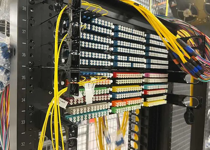
The fiber optic patch panel guide also covers service access and routing. Crowded connections can make controlled inspection difficult even when the correct tools are available.
Prepare a Cleaning Kit RFQ
Include these details in a request for quotation:
- Connector families, single-fiber or multi-fiber format and polish.
- Exposed plugs, recessed adapters or equipment interfaces.
- Inspection instrument and required interface tips.
- Field or bench use, access limitations and storage.
- Approved cleaning method and consumable restrictions.
- Quantities, refill needs, sample evaluation and documentation.
Request an itemized package list. Accessories in a photograph may be optional. Confirm the exact supplied guides, instructions and replacement consumables.
Evaluate a sample on representative interfaces before a larger order. Record any exclusions so later substitutions do not leave part of the installation unsupported.
Fiber Connector Cleaning FAQ
Should new patch cords be inspected?
Yes. Packaging and protective caps do not prove an acceptable end face. Inspect before connection and clean as required by the result and applicable procedure.
Can one cleaner cover every connector type?
Only when explicitly specified for every interface and access arrangement. Verify tips, guides and multi-fiber support separately.
Will cleaning remove scratches?
No. Persistent marks may be scratches, chips or other defects. Escalate the assembly when the approved procedure does not produce an acceptable result.
Does inspection replace loss testing?
No. The installed link still needs the optical measurements and records specified by the project.
Should working links be disconnected for routine cleaning?
Plan inspection when making or remaking a connection and when required by the service procedure. Avoid disconnecting working links solely for an arbitrary cleaning calendar; agree maintenance actions with the network operator.
Specify the Complete Cleaning Workflow
A useful kit combines compatible tools, inspection access, controlled consumables and clear acceptance criteria. Compare the complete workflow instead of only the cleaner’s unit price.
Send Foclink your connector list, access requirements and quantities to discuss the cleaning-tool configuration and items required in your quotation.