
Foclink / Single-mode connectivity
Rack-to-rack
fiber connectivity
12 fibersOS2 single-modeMPO interface
Bring twelve OS2 fibers between rack patch fields in one assembly. Start with the mating ports, follow the position map, then specify the cable route.
Read the port before choosing the cord
Capture both mating interfaces from their drawings. A connector that physically fits can still route a signal to the wrong position.
Guide pinsIdentify which side supplies the pins at each mating pair.
End-face polishMatch the mating end-face finishes specified for the hardware.
Fiber mediumTrace OS2 through the panels and patching to the intended equipment.
Trace the twelve positions
Use the connector drawing’s viewing direction and key orientation to identify position 1. The strip below is a logical index for recording continuity.
Example trace Near cassette Tx → trunk position 01 → mapped far-end position → far cassette Rx. Repeat in reverse for the return fiber. The ordered polarity determines the far-end position.
Inspect the assembly
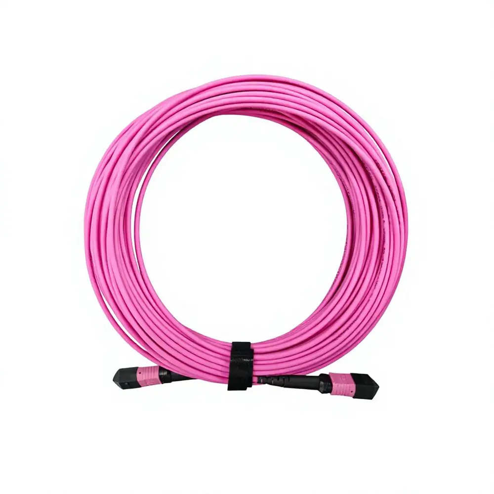
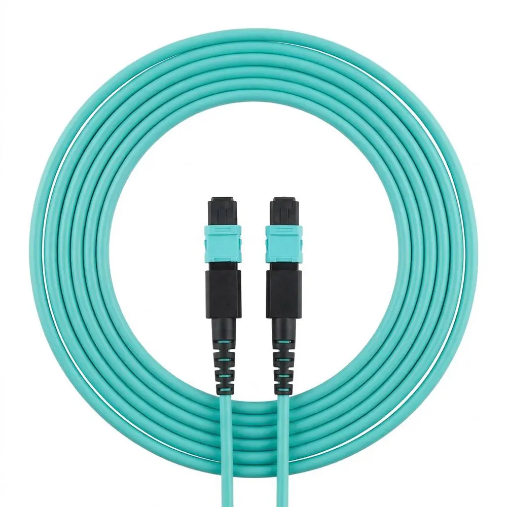
Use the family photographs to review connector and cable construction with your installer. For an order, the approved drawing identifies the actual end A and end B configuration.


Measure the installed route
Follow the intended pathway through both cabinets. Rack-to-rack floor distance misses vertical runs and the cable needed to service each termination.
Planning example. Assumes the 18 m excludes both cabinet allowances. Check the actual route, bend clearance and agreed length tolerance on the order drawing.
Build specification
Use one specification line per route. Keep fixed product characteristics separate from the choices that change the supplied assembly.
- Assembly
- 12-fiber OS2 single-mode MPO trunk
- End A / End B
- Record pinning, polish and mating hardware independently.
- Polarity
- Attach the expected A-to-B position map.
- Mechanical
- State route length, jacket requirement and pathway constraints.
- Acceptance
- Identify test wavelength, reference method and project loss limit.
Commission the complete channel
A continuity result answers one question. Acceptance also depends on where each fiber ends and how much optical power the assembled path loses.
Map the positions
Compare each measured end-to-end position with the approved schedule. Include cassettes in the map if they are inside the test boundary.
Measure the loss
Record the reference method and test wavelength. Compare results with the applicable project budget for that same boundary.
Label the record
Save rack IDs, panel ports, direction and results together so a later circuit move can be traced.
When a link stays dark
Use the symptom to choose the next check. Retest the affected path after each correction.
Continuity passes, but no link
Trace transmitter to receiver through the cassettes and duplex cords. If mapping agrees, review channel loss and equipment configuration.
Only one duplex pair fails
Identify the two positions serving that pair. Compare their routing and measured loss with a working pair before replacing the trunk.
The fault follows a patch move
Compare the new port assignment with the last working record. Verify both directions at the moved port, then update the schedule after retest.
Send a route for configuration review
A panel drawing and a single route line give the technical team a starting point for a build-specific quotation.