
A fiber optic splice closure must fit the cables, splice plan and installation environment together. A high fiber-count label is not enough if the supplied seals do not fit the cable or the trays cannot safely store the required fibers.
This guide helps network buyers, contractors and distributors compare closure configurations before ordering. It covers entry direction, sealing, usable tray capacity, maintenance access and the information needed for a clear quotation.
Start with a cable schedule and a splice diagram. Then compare the complete supplied assembly rather than the empty enclosure alone.
What Does a Fiber Optic Splice Closure Do?
A splice closure protects fiber joints and the managed fiber lengths around them. It commonly contains splice trays, cable anchoring and entry seals. Its role is protection and organization; it does not amplify the optical signal.
Some designs join two cables, while others accommodate branches or access to selected fibers in a through cable. The FOA splice closure overview describes these arrangements and the importance of selecting the hardware for the installation.
A distribution box may also hold splices, but often emphasizes accessible termination or distribution connections. Product names overlap. Specify whether you need protected cable joints, patching interfaces, branch distribution or a combination. Our fiber distribution box guide addresses that separate selection task.
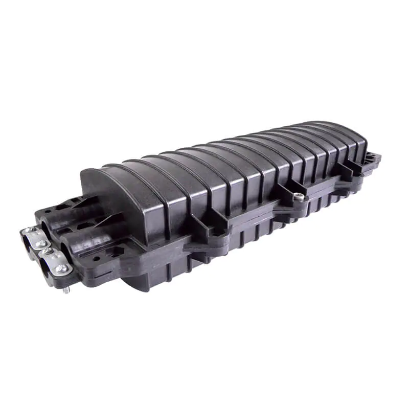

Dome or Inline: Start with Cable Routing
Dome closures typically bring cables into one end; inline designs have entries at opposite ends. Choose from the cable route and service arrangement, then review the actual product drawing.
| Selection item | What to confirm |
|---|---|
| Dome / single-end entry | Cable approach, entry layout, mounting clearance and tray access. |
| Inline / opposite-end entry | Cable route through the joint, service slack and enclosure support. |
| Branching arrangement | Number of branch cables, assigned ports and internal routing. |
| Midspan arrangement | Supported preparation method and storage for uncut elements. |
Neither shape establishes the environmental suitability of a product. Ask for the proposed model’s installation instructions, populated layout and mounting arrangement. Check whether a technician can open and service it in the available working space.
For a repair, include the available cable slack in the decision. A closure that fits the repaired joint still needs an appropriate route for incoming cables and a workable method of securing the assembly.
Match Cable Entries, Seals and the Supplied Kit
Prepare an entry schedule listing each cable’s outer diameter, jacket construction and strength-member arrangement. Ask the supplier to map each cable to an entry and its seal kit. The number of entry openings does not tell you how many cables can be sealed in the supplied configuration.
Do not assume one seal fits the full range of cables in a project. Review the supported cable diameter range and the hardware required for unused entries or later additions. Multi-cable entries need the specified sealing arrangement.
For procurement, request a complete package list: enclosure, trays, splice holders, cable fixing, seals, blanking parts, mounting accessories and any required installation consumables. Identify optional items separately so competing quotations cover the same scope.
Calculate Usable Splice and Tray Capacity
Count the splices that will be installed, then check the tray type and supplied tray quantity. Maximum enclosure capacity may assume additional trays or a different splice arrangement from the standard package.
Planning example: if a design needs 72 individual splices and an approved tray arrangement supports 24 of those splices per tray, the arithmetic requires three trays. The enclosure must also support those trays, the specified holders and the necessary fiber routing. This example is a counting exercise, not a capacity claim for a pictured product.
Reserve expansion capacity in the complete assembly. Spare tray positions are useful only if the future cables can enter, be anchored and be routed without disturbing existing fibers.
For ribbon fibers, confirm the tray and routing system explicitly. Do not infer compatibility from the enclosure’s overall fiber count.
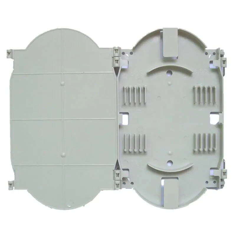
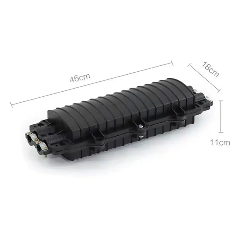
Check Environmental and Sealing Requirements
Describe the actual location: aerial mounting, a wall, a chamber or another specified environment. Ask for model-specific evidence of suitability, including the conditions covered by any ingress-protection or environmental test claim.
A protection label does not replace installation instructions. The assembled condition, fitted seals, cable sizes and unused-entry treatment matter. Do not treat a water-related claim as an unlimited guarantee for every depth, duration or field condition.
The FOA installation guidance calls for appropriate splice protection, secured cable entries and sealing checks. Use the selected closure’s specified procedure; do not invent a pressure-test value or reuse a value from a different model.
For quotations, request the exact model reference on supporting documentation and state the intended installation conditions. Resolve gaps before approving the order.
Plan Midspan Access and Future Re-entry
Midspan access opens part of a cable while retaining fibers or tubes that continue through the location. Confirm that the closure supports the intended access method and has storage space for the uncut elements.
Follow the selected cable and closure instructions for preparation lengths and routing. A generic strip length is not appropriate for every enclosure. The FOA splicing and termination reference explains why preparation and splice protection must match the hardware.
Plan re-entry before installation. Ask which seals or consumables must be replaced, how trays are accessed and how existing connections are protected during additions. A maintenance kit and clear identification schedule can be part of the original order rather than an emergency purchase.
Installation and Acceptance Checklist
- Confirm the supplied kit. Match the enclosure, trays, seal components and mounting parts to the approved order.
- Review the cable schedule. Confirm cable-to-entry assignments, fixing provisions and preparation instructions.
- Install and organize. Secure cables and route fibers according to the selected hardware instructions. Check for trapped fibers before closing trays.
- Verify the assembly. Complete the specified sealing and optical checks. Follow the applicable bonding arrangements where conductive cable components are present.
- Document the handover. Record cable IDs, splice mapping, test results, installed parts and spare capacity.
The FOA outside-plant design reference emphasizes component planning and documentation. Agree the project’s test procedure and acceptance limits before work begins.
Turn Your Splice Plan into a Clear RFQ
Send your project details
- Cable count, diameters and construction.
- Initial splice count and planned additions.
- Branch or midspan arrangement.
- Mounting location and environmental conditions.
- Quantity, delivery destination and required documentation.
Confirm what the quotation includes
- Tray quantities and compatible splice holders.
- Seal kits assigned to each cable entry.
- Cable fixing and mounting accessories.
- A populated drawing and itemized parts list.
- Sample requirements, exclusions and replacement consumables.
Compare quotations against the same cable schedule and parts list. For sample review, use representative cable sizes and check access to the intended trays.
Ready to discuss a configuration? Send Foclink your project details and splice plan using the enquiry link below.