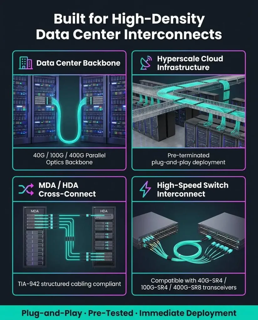
As data centers move from 10G links to 40G, 100G and 400G networks, they need to install more fiber connections in less rack space. Connecting every optical channel with individual LC duplex patch cords can make cabling crowded, time-consuming and difficult to maintain.
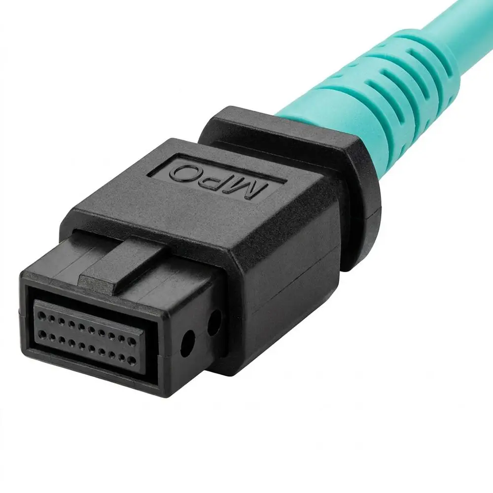
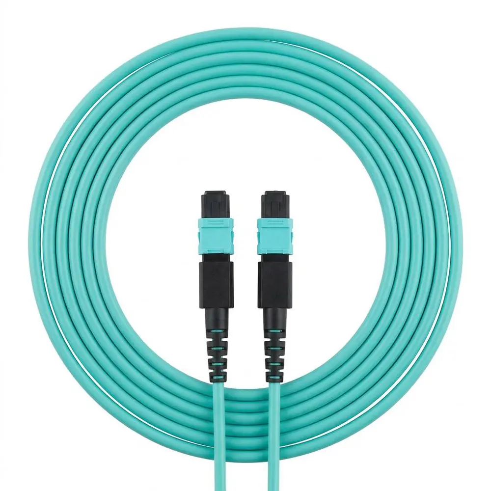
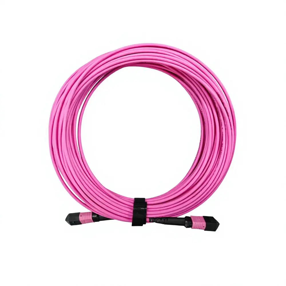
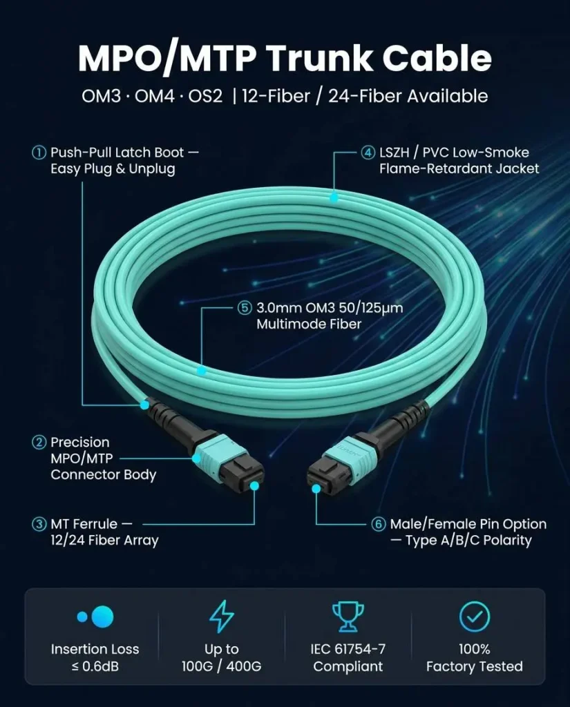
An MPO fiber patch cord combines multiple optical fibers in a single connector. It allows several transmit and receive channels to be connected at once, making it a practical solution for high-density data center cabling, parallel optical transmission and pre-terminated fiber networks.
However, selecting an MPO cable involves more than choosing the correct length. Fiber count, polarity, connector gender, fiber grade, end-face type and insertion loss must all match the equipment and cabling architecture. A mismatch in any one of these areas may prevent the link from working.
What Is an MPO Fiber Patch Cord?
MPO stands for Multi-Fiber Push-On. It is a multi-fiber connector format that places several optical fibers in one rectangular ferrule. Common configurations include 8, 12, 16 and 24 fibers, although higher fiber counts are also available for specialized applications.
Unlike an LC connector, which normally terminates one fiber, an MPO connector can connect multiple optical channels with a single push-pull operation. This makes MPO cabling useful for applications where installation speed, port density and organized cable management are important.
MPO vs MTP: What Is the Difference?
MPO is an internationally recognized connector interface. MTP is a registered brand of MPO connector developed by US Conec. In other words, an MTP connector is a type of MPO connector, but not every MPO connector is an MTP connector.
MTP connectors include proprietary mechanical features intended to improve alignment, durability and serviceability. Both MPO and MTP products can be used in high-density fiber systems, provided their specifications are compatible.
Common MPO Fiber Counts
The correct fiber count depends on the optical transceiver, transmission standard and cabling design. More fibers do not automatically mean better performance.
Choosing Between OM3, OM4 and OS2 Fiber
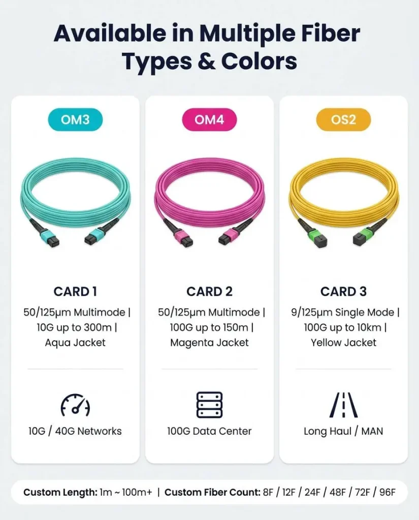
MPO cables are available with multimode and single-mode fiber. The correct option must match the optical modules installed at both ends of the link.
OM3 Multimode Fiber
OM3 is a laser-optimized multimode fiber commonly used for short-distance data center connections. For example, 40GBASE-SR4 can typically reach up to 100 meters over OM3, while 100GBASE-SR4 is generally specified for up to 70 meters.OM3 may be suitable when the link is short, the existing infrastructure already uses OM3, and the required transmission standard supports the planned distance.
OM4 Multimode Fiber
OM4 offers higher modal bandwidth than OM3. It is widely selected for new high-speed data center deployments because it provides additional distance margin for many multimode applications.As a common example, 40GBASE-SR4 can typically reach up to 150 meters over OM4, while 100GBASE-SR4 is commonly specified for up to 100 meters.
OS2 Single-Mode Fiber
OS2 fiber is used for longer transmission distances and single-mode parallel optical applications. The actual reach depends primarily on the transceiver standard rather than the patch cord alone.OS2 MPO cables are commonly used for data center interconnects, telecom equipment, campus networks and high-speed single-mode links such as certain 100G and 400G applications.
Understanding MPO Polarity: Type A, Type B and Type C
Polarity determines how transmit fibers at one end of a link connect to receive fibers at the other end. It is one of the most important specifications in an MPO cabling system.
A link can have the correct fiber type and connector shape but still fail if its polarity does not match the transceivers, adapters, cassettes and patch cords used in the channel.
Type A: Straight-Through
In a Type A cable, fiber position 1 connects to position 1, position 2 connects to position 2, and so on. Type A is commonly called a straight-through cable.Additional polarity management elsewhere in the channel is normally required to achieve the correct transmit-to-receive relationship.
Type B: Reversed
In a Type B cable, the fiber positions are reversed. Position 1 connects to the last position, position 2 connects to the second-to-last position, and so forth.Type B is widely used for direct parallel optical links such as many SR4 applications because it can connect transmit channels at one end to receive channels at the other. However, it should not be treated as a universal choice for every network.
Type C: Pair-Flipped
Type C reverses adjacent fiber pairs. It is mainly associated with certain duplex breakout and cassette-based cabling architectures.Before ordering, document the complete channel from the first transceiver to the second transceiver. Include every patch cord, adapter, cassette and trunk cable. Polarity should be verified for the entire link, not just one component.
MPO Male vs Female Connectors
A proper connection normally mates one pinned connector with one unpinned connector. Two male connectors cannot be connected correctly because both sides contain pins. Two female connectors lack the pins needed for precise alignment.The required gender depends on the transceiver or adapter interface. Many optical transceivers have male MPO ports and therefore require female cable connectors, but this must be checked against the equipment datasheet.
UPC and APC MPO Connectors