
A fiber optic patch cord order should describe both ends of the connection, not just the cable length. Connector style, polish, fiber category, routing and acceptance tests all affect whether the delivered assembly fits the project.
This guide is for buyers specifying individual-fiber patch cords for racks, panels and equipment connections. It provides a repeatable order format and a practical incoming-inspection checklist. Multifiber assemblies require additional mapping decisions covered in our MPO cable selection guide.
Table of Contents
ToggleBuild the Order Around Two Defined Endpoints
Begin with the installed interfaces. Record the equipment or panel connection at end A and end B separately, including the connector family and required end-face finish. A photograph helps identify the physical arrangement, but the port documentation and approved design should establish the specification.
Write the order as a sequence: end A → end B → fiber category → fiber count → assembly construction → length → acceptance requirements. This prevents a short description such as “single-mode jumper” from being treated as a complete technical requirement.
Where several rack locations need different lengths or interfaces, create one line item per configuration. Keep each line tied to a drawing or port schedule so a revised requirement does not silently change every assembly in the order.
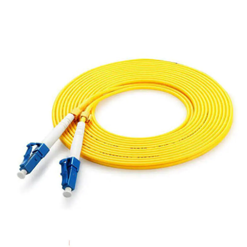

Match Connector Style and Polish at Each End
Connector family and polish describe different aspects of a connection. The housing must fit the interface, and the mating end faces must be compatible. A connector that appears to fit mechanically is not sufficient evidence of a correct optical connection.
APC and UPC must not be mated directly to one another. A hybrid patch cord can have a different compatible termination at each end: each end still has to match the port it actually enters. The Fiber Optic Association’s connector-matching example illustrates this distinction for test connections.
Specify each end independently:
- End A: connector family, polish and simplex or duplex arrangement.
- End B: the same fields, checked against its own interface.
- Routing: boot clearance, access for release latches and any required identification.
- Evidence: the approved drawing or port schedule used to select those terminations.
Color can help technicians recognize an assembly, but it should support written identification rather than replace it. Specify the exact interface in the purchase order and on the packing list.
Specify Fiber Type, Count and Polarity
Select the fiber category required by the link design and connected equipment. Do not treat a connector name such as LC as a specification for the fiber inside it. Request the actual fiber designation in the quotation and check it against the installed cable plant.
Separate the number of fibers from the mechanical arrangement. A simplex assembly carries one fiber; a duplex assembly groups two. For a two-fiber transmit/receive link, document the complete end-to-end path so the transmitter reaches the receiver. The FOA explanation of link polarity shows why patch-cord orientation cannot be assessed independently of the permanent cabling.
Do not order a crossed or straight arrangement solely by habit. Record the required mapping, the viewing direction used on drawings and the labels used by the installation team.
Choose Length for the Actual Cable Route
Measure the intended cable-management route, including entry and exit paths, rather than only the distance between ports. Allow enough service length to disconnect and maintain the assembly without leaving uncontrolled loops in front of equipment.
Ask how the supplier defines the quoted length and its tolerance. A connector-to-connector dimension and a jacket-length dimension can produce different delivered assemblies. Put the agreed measurement points on the drawing where space is critical.
Confirm cable diameter, boot shape and the assembly’s permitted bend radius against the route. Do not infer a bend limit from appearance or use a generic number for every construction. Review the patch panel layout together with the cord schedule, particularly where doors or sliding trays move during service.
Match the Construction to the Installation
The intended installation determines the jacket and mechanical requirements. State whether the assembly will remain inside a protected rack or pass through another environment. Include the relevant temperature, exposure and installation requirements in the purchasing specification.
Ask for documentation covering the exact supplied construction when a project requires a fire rating or other compliance evidence. A jacket description alone is not proof that every required test or approval applies to that product. Keep the requested evidence specific, rather than collecting unrelated certificates.
Agree on Optical Tests Before Ordering
Agree on acceptance before ordering. A useful test requirement identifies the measured quantity, test method, wavelengths, reference arrangement and pass/fail limits. “Low loss” without those details is not a comparable acceptance criterion.
Insertion-loss results depend on which connections are included in the measurement. In a single-ended patch-cord test, reversing the assembly allows the other connector to be evaluated. The FOA patch-cord test procedure explains the method. Request results that match the agreed setup rather than comparing numbers from different setups as if they were equivalent.
If the project also specifies return loss, request that measurement explicitly with its method and limits. An insertion-loss result does not replace it. Link records to the supplied assembly or batch, as agreed in the purchase order.


Use a Receiving Checklist Before Installation
Receiving checks should confirm both the ordered configuration and the condition of the delivered assemblies. Use the approved sample or drawing as a reference, and keep discrepancies separate from accepted stock until they are resolved.
- Match the paperwork: quantity, line-item reference, fiber designation, both terminations and length.
- Check the assembly: jacket damage, sharp kinks, boots, connector housings and labels.
- Inspect end faces before connection: use suitable inspection equipment, clean where needed and inspect again. Follow our connector cleaning and inspection guide.
- Review test evidence: confirm the method and results correspond to the agreed acceptance criteria.
- Verify the installed path: confirm routing and polarity before handing the link over for application testing.
Send a Complete Patch Cord RFQ
A clear RFQ brings the assembly definition and delivery requirements together. Use the two groups below as a final check, and ask suppliers to identify deviations explicitly so price comparisons are based on the same scope.
Define the assembly
- End A and end B connector family and polish.
- Fiber designation, count and required mapping.
- Length schedule, measurement points and tolerance.
- Cable construction, routing and environment.
Define the delivery
- Quantity per configuration and identification format.
- Required inspection and optical test records.
- Project-specific documentation requirements.
- Packaging, sample review and delivery requirements.
Example RFQ wording: “Please quote the attached patch-cord schedule. Confirm each end termination, fiber designation, construction, measured length and tolerance. List the proposed test method and acceptance limits for review, and identify any differences from the drawing before production.”
Send Foclink your port schedule and routing requirements through our contact page. A complete configuration makes quotations easier to compare and reduces ambiguity when samples and production orders are reviewed.